My shopping cart
Your cart is currently empty.
Continue Shopping

By R&D
Published on January 5th, 2024
As an Amazon associate, we earn from qualifying purchases.
This article outlines the procedures to diagnose and confirm Diagnostic Trouble Code (DTC) P0420 on a 2017 GMC Yukon and to replace the Catalytic Converter(s) to resolve the issue.
In cases where the Malfunction Indicator Lamp (MIL) on your vehicle’s dashboard is illuminated and the Engine Control Module (ECM) has stored DTC P0420 (Catalyst System Low Efficiency), it indicates the ECM has detected that the catalytic converter on Bank 1 is not functioning properly.
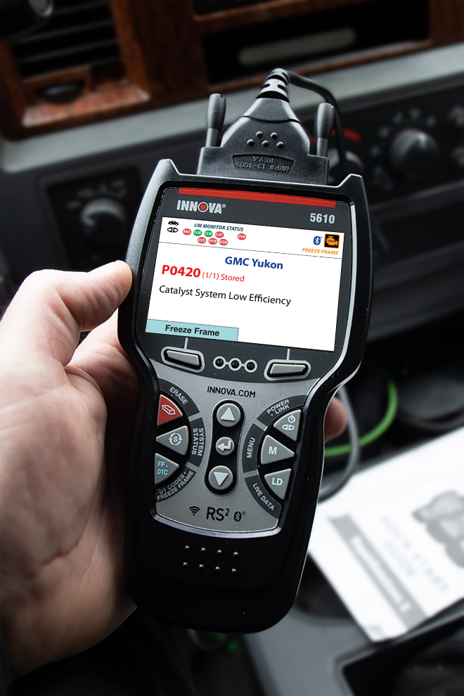
The catalytic converter is a component of the exhaust system. Its purpose is to reduce harmful emissions by converting them into less harmful substances. Bank 1 refers to the side of the engine where cylinder 1 is located. Operating your vehicle with a malfunctioning catalytic converter will result in increased tailpipe emissions and may damage your vehicle’s engine.
To correct this issue, you will inspect the vehicle’s exhaust system, test the oxygen sensors and catalytic converter(s), and replace the catalytic converter(s) as needed.
Symptoms of DTC P0420 include:
Possible causes of this fault include:
On a 2015 - 2018 GMC Yukon V8-5.3L, replacing the catalytic converter may resolve DTC P0420.
| Table header 0 | Step Time required (hour) Sections Cautions | 5 1.6 3 0 |
|---|---|---|
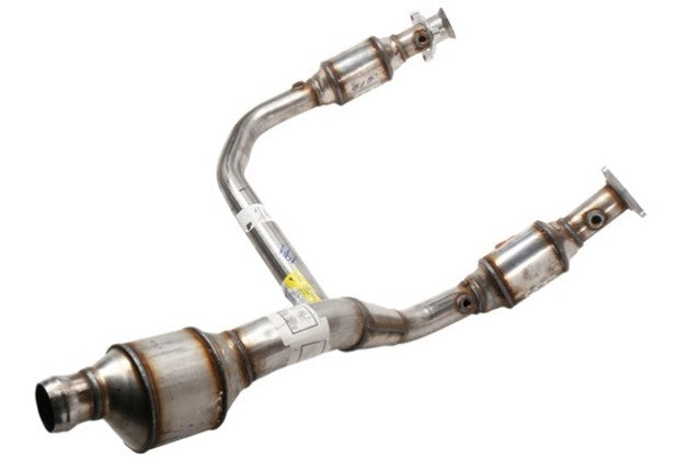
| Model | Part Number | Part name |
| GMC Yukon V8-5.3L | 23486656 | Three Way Catalytic Converter |
(This image is for illustrative purposes only and may not match the actual part number)
Find the perfect scanner in 1 minute
During your initial inspection, check for obvious mechanical signs such as torn inlet boots, missing or broken vacuum tees, and/or cracked, broken, or disconnected wire harnesses. Make sure all harness connectors are properly placed in the connectors and holders. This will prevent potential open or short-circuit issues. Also, check the connector for corrosion, frayed wiring, and damaged terminals.
Check for exhaust leaks at the exhaust manifold and exhaust pipes, specifically at or around the Heated Oxygen Sensor (HO2S) and Catalytic Converter. Inspect for visual or physical damage, severe discoloration, substrate rattling noise and/or potential partial restrictions. Also, check the muffler for blockage due to catalytic materials.
Inspect the valve clearance, excessively tight exhaust valves can set this code. Refer to the Vehicle Emissions Warranty Manual for time and mileage coverage of emissions-related fault(s). For additional information, refer to the Service Manual or applicable Technical Service Bulletin (TSB).
Step 1: Start the engine and allow it to idle. The engine must be at operating temperature.
Step 2: When you look at Fuel Trim at idle, these numbers are greatly influenced by vacuum leaks. Check Long-Term Fuel Trim (LTFT) at idle, 1500, 2000, and 2500 RPM. The value should be less than +/- 10%.
If the value is greater than this, correct this problem before continuing. Look for fuel pressure, leaking injectors, vacuum leaks, Mass Air Flow (MAF) sensor faults, etc.
If the value is within specification, go to step 3.
Step 3: Raise the engine to 2000 RPM for approximately 3 minutes. Make sure the Closed Loop operation has been achieved.
Step 4: Return the engine to idle. Using a Scan Tool in Live Data (LD) graphing mode, monitor HO2S Bank 1 Sensor 2 voltage. The voltage should slowly fluctuate between 0.1–0.8V.
If the voltage is fluctuating rapidly between 0.1–0.8V, suspect a defective catalytic converter. Before replacement, look for misfires, over-fueling, physical damage, etc.
If the voltage did not follow this pattern, replace the HO2S sensor. Perform Repair Validation.
If the same DTC sets, perform Repair Validation.
Step 1 – Use a lift to raise the vehicle.
Step 2 – If the vehicle is equipped with 4-wheel drive (4WD), detach the front U-joint yoke retainer bolts from the front axle propeller shaft.
Step 3 – Disconnect all heated oxygen sensors on bank 1 and bank 2.
Step 4 – Remove the exhaust front pipe from the exhaust muffler.
Step 5 – Remove the right catalytic converter from the right exhaust manifold.
Step 6 – Remove the left catalytic converter from the left exhaust manifold.
Installation is accomplished in the reverse order of removal.
Step 1: Clear DTC(s) and Freeze Frame (FF) information.
Step 2: Perform the Key ON Engine OFF (KOEO) and Key ON Engine RUNNING (KOER) tests or follow the catalytic converter drive cycle requirements.
Step 3: An optional method to validate the repair would be to operate the vehicle with the conditions recorded in the FF data.
Step 4: Check for pending or stored DTC(s). If none are found, repair is complete.
NOTE: Some new catalytic converters may require a break-in period of approximately 100 miles.


Hop in the discussion board on our community site!
It's a place where we help each other answer questions. Like Reddit but for automotive lovers.
SUBSCRIBE & GET ACCESS TO LIMITED-TIME OFFERS
